
Porsche 964 – Targa with Tiptronic Gearbox from 1991
Rear Spoiler Issue
Fault reported: The spoiler was not functioning correctly. The Warning Signal was not clearing when the speed reached 8 km/h. The spoiler was not rising automatically at 80 km/h. The spoiler would extend but would not retract automatically when the speed dropped below 15 km/h. The spoiler functioned correctly under manual control.
The electrical schematic for the spoiler controller was analysed. The electronic components of the board were tested and the Warning transistor, the Retract transistor and another Control transistor were changed as they were faulty. All six electrolytic capacitors were changed as their capacitance values were not in specification.
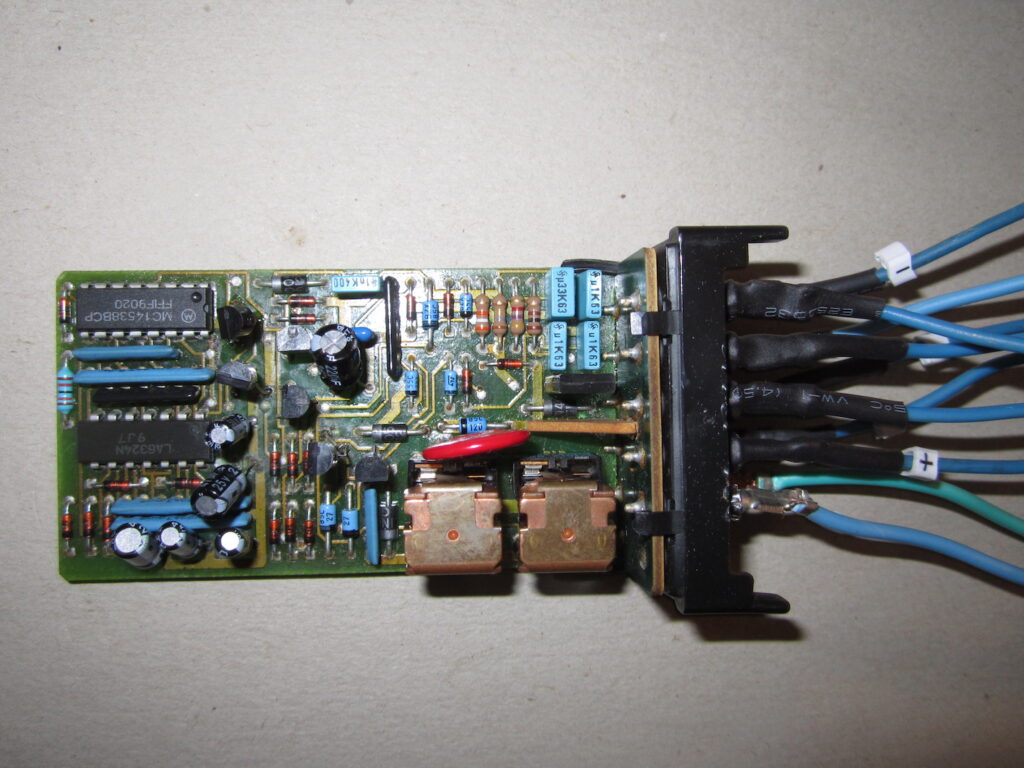
The above photograph shows the Spoiler Controller Board removed from the car. Various test wires have been connected to verify the operation.
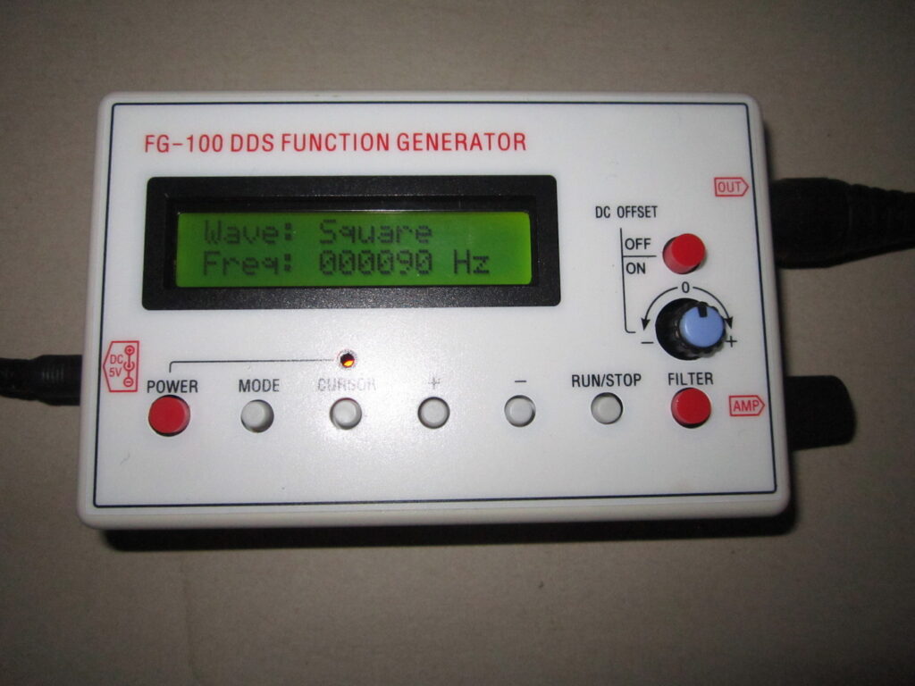
To test the board out of the vehicle it is necessary to replicate the road speed signal. At 8 km/h (or 9 Hz) the Warning Signal will be cleared. The purpose of the Warning Signal is to test the presence of the speed signal from the Tiptronic gearbox. In cars with a manual gearbox the speed signal comes from the ABS sensor in the front left hub.
At approximately 80 km/h (or 84 Hz) the spoiler should rise automatically. When the speed drops below 15 km/h (or 17 Hz) the spoiler should retract automatically. In the above picture the signal generator will be used to replicate the speed signal. A square wave signal of precise frequency can be sent to the board to replicate the desired road speed.
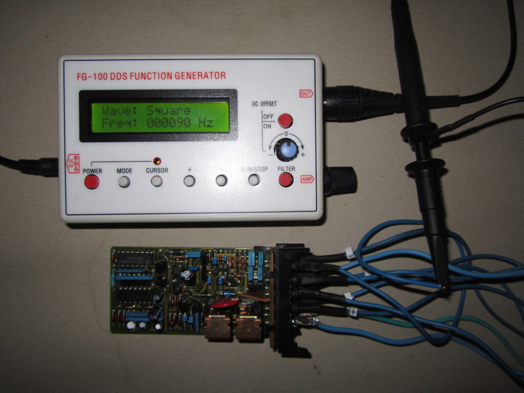
The above picture shows the board connected to the signal generator. In this case the output signal is 90 Hz and the spoiler should rise.
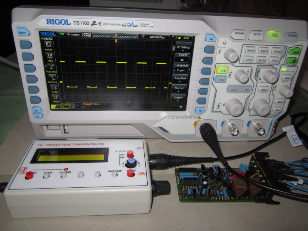
In the above picture we can see the square wave of 90 Hz which is equivalent to approximately 85 km/h. At this speed the output relay has supplied power to the spoiler drive motor and the spoiler has extended. There are extend and retract limit switches to cut the power of the motor when the extend and retract conditions have been met.
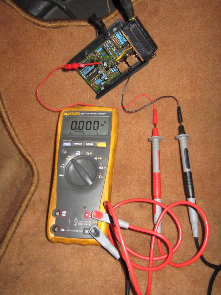
In the above picture the Spoiler Controller Board is being tested in the vehicle. The Warning Signal output is being verified. 0.000 VDC means the Warning Signal is active. This signal changes to battery voltage (14 VDC) when the speed exceeds 8 km/h. At this point the Warning Signal is no longer active.
Solutions: The drive transistors for the Warning signal, Extend and Retract motors were replaced. Also, the 6 electrolytic capacitors were replaced as their capacitance values were incorrect. Replacing these parts repaired the non-functioning spoiler mechanism.
Speedometer Issue
Fault reported: The speedometer was not showing the car’s speed when driven. The odometer (showing the total distance travelled) was not incrementing. Also, the tripmeter in the tachometer was not incrementing.
The speedometer on this version of the 964 is unusual. The gearbox is a Tiptronic (automatic gearbox made by ZF) and the gear selector position is displayed in the speedometer gauge. The odometer is driven by a stepper motor that receives an electronic pulse from the front left wheel ABS sensor. The same pulse signal drives the analogue speed needle. The speedometer resends the speed pulse signal to the tachometer. This car has the OBC (on-board computer) option. This OBC has a special digital LCD (liquid crystal display) field at the lower section of the tachometer. The OBC displays the average speed, distance to next tank fill, tripmeter, instantaneous speed, average fuel consumption, and outside temperature.
This car was originally registered in the USA so the information in the OBC is in Imperial units – miles, gallons, Fahrenheit. The car was then sold to Canada where the speedometer gauge face was changed to kilometres. The analogue speedometer needle shows the speed in kilometres. The odometer though still records the distance in miles. The OBC information in the tachometer still shows Imperial units.
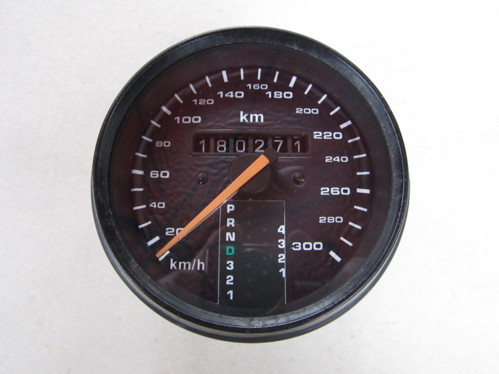
The electrical schematics were referenced and the signal from the ABS circuit was traced from the front left wheel hub to the rear of the speedometer gauge. All the connections and signals were good. The next step is to inspect the speedometer internally for any faults.
The rear of the speedometer can be seen below. Note the paper sticker stating it is the IMP/MILE (Imperial/mile) version.
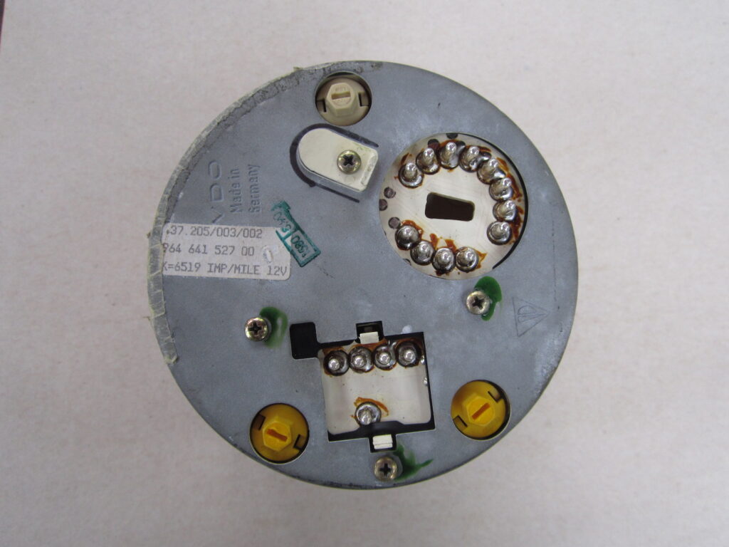
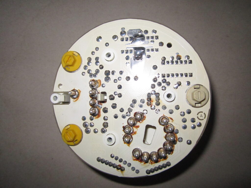
The front face of the speedometer gauge was removed to access the internal electronics. In the next photo we can see the rear of the control circuit board. All the solder joints were checked for continuity and a few were open-circuit. This is usually caused by age and road vibrations. The solder joints were remade. The flux residues are evident as brown stains on the board. The dry solder joints are the most likely cause of the dead speedometer needle.
To repair the odometer, it is necessary to remove the needle, gauge front face and then the stepper motor. The stepper motor is shown in the photo below. This stepper motor has 8 magnetic poles. Each pulse from the ABS circuit causes the motor to rotate 1/8th of a turn. After 8 pulses it has completed one rotation. The 8-pole stepper motor is used in the Imperial speedometers for the odometer.
The kilometre speedometer uses a 5-pole stepper motor for the odometer. The ratio of miles to kilometres is 5:8 approximately (5:8.047 precisely). The only difference internally between the mile and kilometre speedometers is the use of a different stepper motor to act as a distance convertor.
The stepper motors are not available as a separate part so it is not possible to easily convert the odometer from miles to kilometres or vice versa. This odometer will have to stay as an Imperial version, even though the speedometer reads in kilometres.
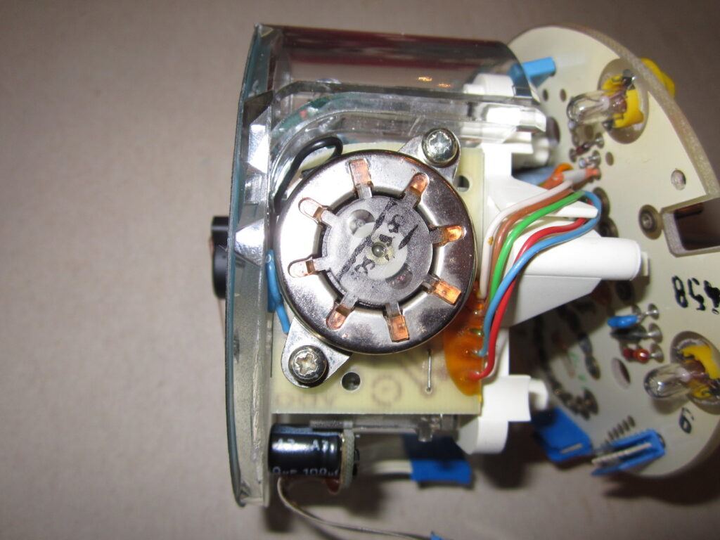
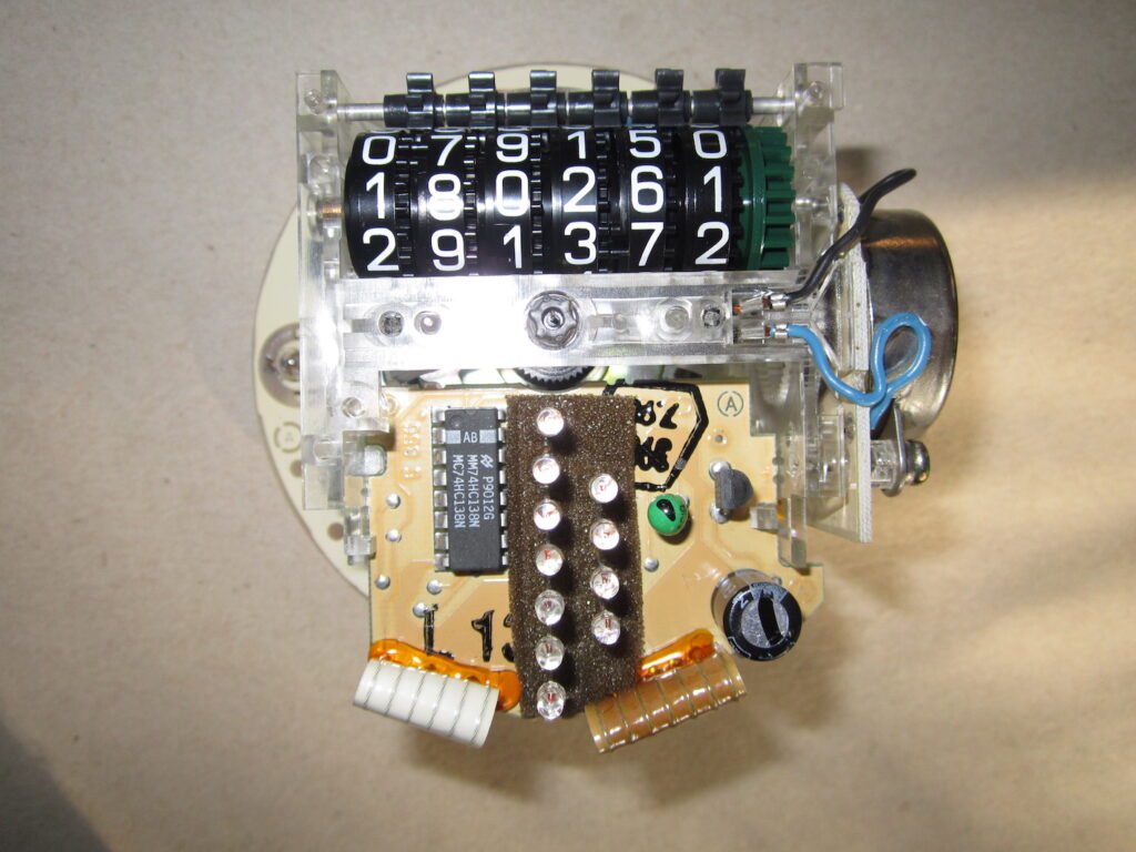
The usual cause of odometer failure is the nylon plastic drive gears between the stepper motor and the odometer digits green drive gear. Usually the teeth in the nylon gearwheels break off. The photo below shows the odometer digits and the green drive gear.
Finally, we have the broken drive gears that connect the stepper motor and the odometer.
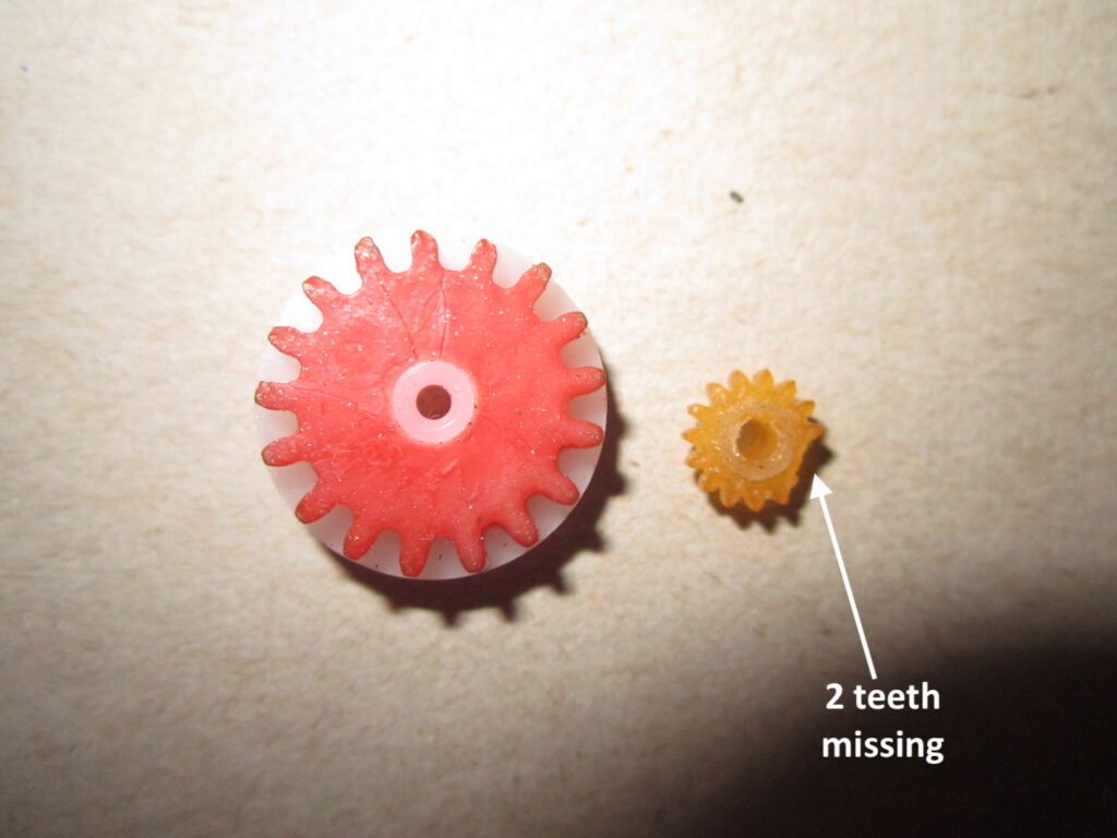
The gear wheels were replaced, the speedometer was reassembled and tested on the car. The speedometer needle now reads the correct speed and the odometer and OBC (in the tachometer) now read correctly.
Solutions: The solder joints on the printed circuit board were remade and this fixed the non-functioning speedometer and OBC issue. The faulty odometer was fixed by replacing the broken nylon gearwheels in the drive mechanism.
Copyright 2026 CMT Europe bv